Chain Maintenance
Maintenance Schedule
Regular chain maintenance is important to obtain maximum life. In a correctly sized and installed drive, chain can be expected to last for approximately 15,000 hours.
The following maintenance schedule is suggested.
AFTER 3 MONTHS
• Check chain adjustment and rectify if necessary.
• Change oil, oil filter, and clear the sump.
ANNUALLY
• Carry out the above checks.
• Check for wear on sideplates.
• Check for chain elongation.
• Check cleanliness of components:
- Remove any accumulation of dirt or foreign materials.
• Check for shaft and sprocket alignment.
• Check for wear on sprockets.
• Check the condition of the lubricant.
• Check the lubrication system:
- Feed pipes are not clogged.
- Lubrication schedule is being followed
(manual lubrication).
- Drip rate is sufficient (drip system).
- Oil level is correct (drip, bath and disc systems).
- Pump is working (stream system).
Chain Protection
A new Chain should always be stored in its box and/or bag until installation. Chain is lubricated at the factory, but this lubrication will not stand up to outdoor conditions, particularly in a saltwater atmosphere. Unprotected, lubricated chains will become contaminated with grit and other materials that will harm the chain and tend to clog strainers, filters, and oil lines. A roller chain is a precision-made series of bearings that will perform best if handled and stored in correct conditions.
Lubrication
Chain drives should be protected against dirt and moisture and lubricated with good quality, non-detergent petroleum-based oil. A periodic change of oil is desirable as already outlined. Heavy oils and greases are generally too stiff to enter the chain working surfaces and should not be used. Care must be taken to ensure that the lubricant reaches the bearing area of the chain. This can be done by directing the oil into the clearances between the inner and outer linkplates, preferably at the point where the chain enters the sprocket on the bottom strand. The table below indicates the correct lubricant viscosity for various ambient temperatures. For the majority of applications in the above temperature range, a multigrade SAE 20/50 oil is suitable.
USE OF GREASE
As mentioned above, the use of grease is not recommended. However, if it is essential to use grease lubrication, the following points should be noted:
• Limit chain speed to approximately 13 feet/sec.
(4 meters/sec.)
• Applying normal greases to the outside surfaces of a chain only seals the bearing surfaces and will not work into them. This causes premature chain failure. Grease must be heated until fluid and the chain are immersed and allowed to soak until all air bubbles cease to rise. If this system is used, the chains need regular cleaning and regreasing at intervals, depending on the drives, power, and speed.
ABNORMAL AMBIENT TEMPERATURES
For elevated temperatures up to 482°F (250°C), dry lubricants such as colloidal graphite or MoS2 in white spirit or poly-alkaline glycol carriers are most suitable.
Conversely, at low temperatures between -40°F and 23°F (-40°C and -5°C), special low temperature initial greases, and subsequent oil lubricants are necessary. Lubricant suppliers will give recommendations.
LUBRICATING METHODS
There are four basic methods for lubricating chain drives. The recommended methods are shown in the rating charts, which are determined by the chain speed and power transmitted.
TYPE 1: Manual Lubrication
Oil is applied periodically with a brush or oil can, preferably once every eight hours of operation. Volume and frequency should be sufficient to just keep the chain wet with oil and allow penetration of clean lubricant into the chain joints.
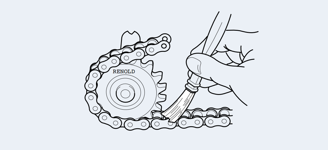
Applying lubricant by aerosol can be satisfactory under some conditions, but it is important that the aerosol lubricant is of an approved type for the application, such
as that supplied by Renold Jeffrey. This type of lubricant penetrates into the pin/bushing/roller clearances, resisting both the tendency to drip or drain when the chain is stationary and centrifugal “flinging” when the chain is moving.
TYPE 2: Drip Lubrication
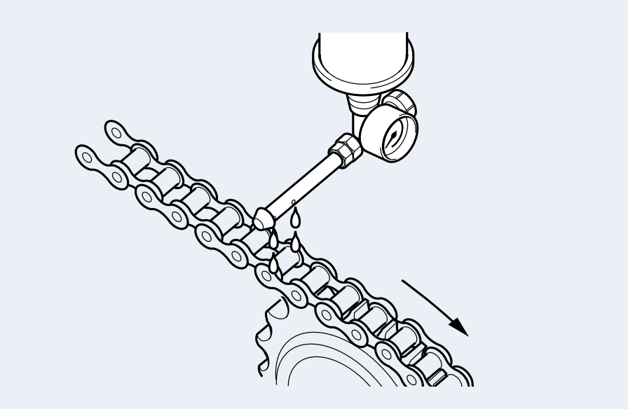
Oil drips are directed between the linkplate edges from a drip lubricator. Volume and frequency should be sufficient to allow penetration of lubricant into the chain joints.
TYPE 3: Bath or Disc Lubrication
With oil bath lubrication, the lower strand of chain runs through a sump of oil in the drive housing. The oil level should cover the chain at its lowest point during operation.
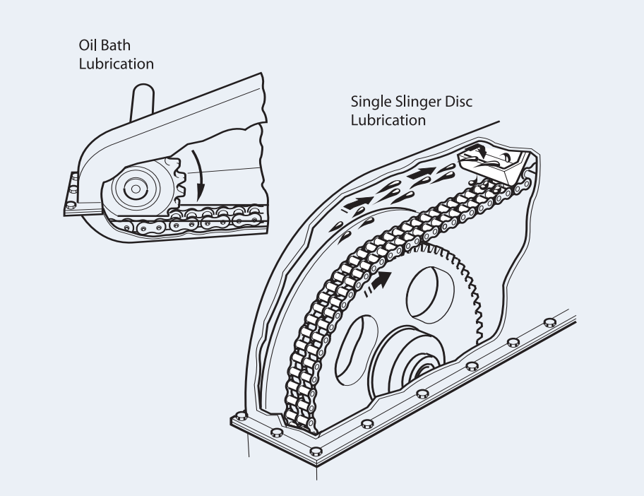
With slinger disc lubrication, an oil bath is used but the chain operates above the oil level. A disc picks up oil from the sump and deposits it on the chain by means of deflection plates. When such discs are employed, they should be designed to have peripheral speeds between 590 and 7,350 ft./min.
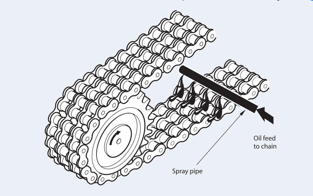
TYPE 4: Stream Lubrication
A continuous supply of oil from a circulating pump or central lubricating system is directed onto the chain. It is important to ensure that the spray holes from which the oil emerges are in line with the chain edges. The spray pipe should be positioned so that the oil is delivered onto the chain just before it engages with the driver sprocket. This ensures that the lubricant is centrifuged through the chain and assists in cushioning roller impact on the sprocket teeth. Stream lubrication also provides effective cooling and impact damping at high speeds. It is, therefore, important that the method of lubrication specified is closely followed.
EFFECT OF TEMPERATURE
During operation an important factor to control in a drive system is the chain and chain case temperature. Depending on the severity of the drive service, continuity of use, etc., special attention to the lubrication method may be required. Chain temperatures above 212°F (100°C) should be avoided if possible due to lubricant limitations, although chain can generally give acceptable performance up to approximately 482°F (250°C) in some circumstances. One way of improving the effectiveness of the lubrication and its cooling effect is to increase the oil volume (up to 1.2 gallons per minute or 4.5 liters per minute per chain strand) and incorporate a method of external cooling for the oil.
Measuring Chain Wear
A direct measure of chain wear is the extension in excess of the nominal length of the chain. Chain wear can, therefore, be ascertained by length measurement in line with the instructions given below.
• Lay the chain, which should terminate at both ends with an inner link (roller link), on a flat surface and, after anchoring it at one end, attach a turnbuckle and a spring balance to the other end.
• Apply a tension load by means of the turnbuckle amounting to: For single-strand chain: (25.4 x P)2 x .173 lbs For double-strand chain: (25.4 x P)2 x .351 lbs For triple-strand chain: (25.4 x P)2 x .524 lbs

Where P is the pitch in inches. In the case of extended pitch chains (e.g. chains having the same breaking load and twice the pitch) apply a measuring load as for the equivalent short pitch chains. As an alternative to the use of a turnbuckle and spring balance, the chain may be hung vertically and the equivalent weight attached to the lower end.
• Measure length ‘M’ (see diagram) in inches from which the percentage extension can be obtained from the following formula:
Percent Elongation = M - (X x P) x 100 X x P Where X = number of pitches measured P = pitch in inches
• As a general rule, the useful life of the chain is terminated and the chain should be replaced when the percentage extension reaches 2 percent (1 percent in the case of extended pitch chains). For drives with no provision for adjustment, the rejection limit is lower, dependent upon the speed and layout. A usual figure is between 0.7 and 1.0 percent extension.
CHAIN WEAR GUIDE
A simple to use chain wear guide is available from Renold Jeffrey for most popular sizes of chain pitch. Please contact your sales office for details.
Riveting Chain Endless
ROLLER CHAINS UP TO 2.5” PITCH (63.5mm)
• Insert the bearing pins of the outer link through the inner link of the chain to be joined. If multi-strand chain, assemble intermediate plates at the same time.
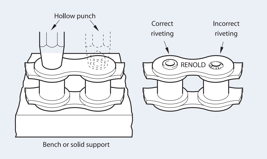
• Provide support for the outer link while assembling the separate outer plate. This has a force fit and is driven onto the bearing pins using a hollow punch alternatively on each pin. Drive up to the shoulder on the shouldered bearing pins. Where there is no shoulder the plate is driven to the point of similar clearance between outer and inner links as with the adjacent chain.
• Still supporting the outer link, rivet the bearing pin ends, taking care to finish with a neat uniform spread having a similar appearance to the machine-riveted pins in the adjacent chain. The force required to spread the pin end will vary with the pitch of the chain; excessive riveting force should always be avoided. Except where final chain joining in position is necessary, the work should be carried out on a bench.
• Check that the newly fitted link articulates freely in the adjacent inner link.
Chain Length Alterations
All drives should be designed, whenever possible, with sufficient overall adjustment to ensure the use of an even number of pitches throughout the useful life of the chain.
Offset links should never be used on highly loaded or high-speed chain drives.
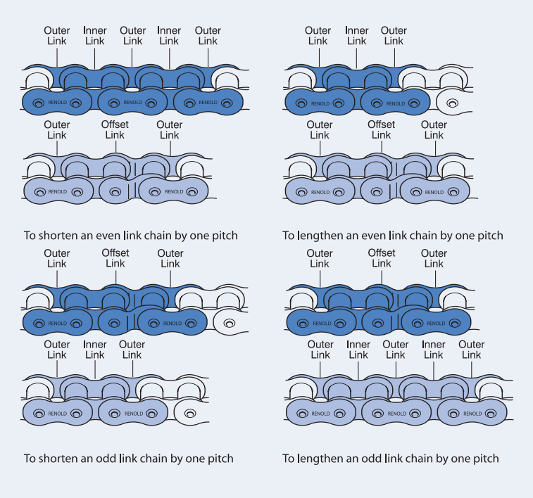
In less arduous conditions where the use of an offset link is unavoidable, the diagrams below show how length alteration can be accomplished.
A chain with an even number of links requires the incorporation of an offset link to effect an alteration of one pitch.
Chain with an odd number of links incorporates an offset link, which must be removed to effect an alteration of one pitch.
By removing the parts shown in dark shading and substituting those in light shading, a chain can be shortened or lengthened by one pitch.
No link that relies on a press fit for assembly should be reused after removal. A new link should always be employed.
Pairing and Matching Chains
Any application in which two or more strands of roller chain are required to operate side by side in a common drive or conveying arrangement may involve the need for either pairing or matching. Such applications generally fall into one of the following categories:
Length Matching for Conveying and Similar Applications
Wherever length matching of roller chain is necessary it is
dealt with as follows:
• The chains are accurately measured in handling lengths between 10 feet and 25 feet as appropriate and then selected to provide a two (or more) strand drives that have overall length uniformity within close limits. Though such length uniformity will not necessarily apply to any intermediate sections along the chains, the actual length of all intermediate sections, both along and across the drive, will not vary more than our normal manufacturing limits. However, attachment chains are usually manufactured to specific orders, which are generally completed in one production run so that it is reasonable
to assume that length differences of intermediate sections will be small.
• Chains are supplied in sets that are uniform in overall length within reasonably fine limits and will be within our normal manufacturing limits. It should be noted that chain sets supplied against different orders at different times may not have exactly the same lengths to those supplied originally, but will vary by no more than our normal tolerance of 0.0%, +0.15%.
Pitch Matching Roller Chains
Pitch-matched chains are built up from shorter subsections (usually 1- to 2-foot lengths) which are first measured and then graded for length. All subsections in each grade are of closely similar length and those forming any one group across the set of chains are selected from the same length grade.
The requisite number of groups are then connected to form a pitch-matched set of chains, or alternatively, if too long for convenient handling, a set of handling sections for the customer to assemble as a final set of pitch-matched chain. Suitable tags are fixed to the chains to ensure they are connected together in the correct sequence.
Identification of Handling Lengths
Handling Length 1 | Handling Length 2 | Handling Length 3 | |
A Strand | A-A1 | A1-A2 | A2-A3 |
B Strand | B-B1 | B1-B2 | B2-B3 |
C Strand | C-C1 | C1-C2 | C2-C3 |
Long chains are made up in sections; each section is numbered on end links. Sections should be so joined up that end links with similar numbers are connected. When chains are to run in sets of two or more strands, each strand is stamped on the end links of each section with a letter, in addition to being numbered. Correct consecutive sections for each strand must be identified from the end links and joined up as indicated.
By these means, the actual length of any intermediate portion of one strand (as measured from any one pitch point to any other) will correspond closely with that of the transversely equivalent portion on the other strands, generally within 0.002 in., depending on the chain pitch size.
Pitch Matching Attachments Fitted to Chains
With the sole exception of extended bearing pins, it is not possible to match the pitch of holes in attachments themselves to within very fine limits, due to the additional tolerances to be contended with (bending, holing, etc.).
Color Coding
For customers who wish to match their chains,
Gidi-chain color codes short lengths of chain within specified tolerance bands. These will normally be red, yellow, or green paint marks to indicate lower, mid, and upper thirds of the tolerance band. For even finer tolerance bands, additional colors can be used. Normally a maximum of five colors is more than adequate.
Color | Tolerance |
RED | 0 05% |
YELLOW | 0.10% |
GREEN | 0 15% |
BLUE | For finer tolerances |
WHITE |
Repair and Replacement
SPROCKETS
Examination of the tooth faces indicates the amount of wear that has occurred. Under normal circumstances, this will be evident as a polished worn strip about the pitch circle diameter on each of the sprocket teeth as shown below.
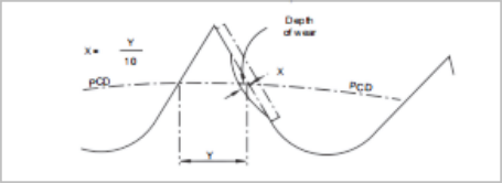
If the depth of this wear “X” has reached an amount equal to 10 percent of the“Y”dimension, then steps should be taken to replace the sprocket. Running new chain on sprockets having this amount of tooth wear will cause rapid chain wear.
It should be noted that in normal operating conditions with correct lubrication, the amount of wear“X”will not occur until several chains have been used.
CHAIN
Chain repair should not, as a rule, be necessary. A correctly selected and maintained chain should gradually wear out over a period of time, (approximately 15,000 hours) but it should not fail. A length extension check as detailed on page 208 will give an indication of the service life remaining.
If a transmission chain sustains damage due to an overload, jam-up, or by riding over sprocket teeth; it should be carefully removed from the drive and given a thorough visual examination. Remove the lubricating grease and oil to make the job easier.
Depending on the damage, it may be practicable to effect temporary repairs using replacement links. It is not, however, a guarantee that the chain has not been overstressed and so made vulnerable to a future failure. The best policy therefore is to remove the source of trouble and fit a new chain.
If a chain has failed two or more times, it is certain the chain will fail again in time. It is advisable to replace the chain immediately. Further repair and use is not recommended.
The entire chain should be replaced because of the following reasons:
• The cost of downtime to the system or machine can often outweigh the cost of replacing the chain.
• A new or even used portion of chain or links assembled into the failed chain will cause whipping and load pulsation. This will likely produce rapid chain failure and will accelerate wear of both the chain and its sprockets.
Assembling Connecting Links
When assembling a connecting link with a slip-fit outer plate, the plate must be pushed down on the pins to permit insertion of the fastener. Always ensure that the closed end of the spring clip is in the direction of rotation.
On a press-fit connecting link, it is necessary to drive the outer plate down far enough on the pins to allow insertion of the two split pins, but not so far as to create a tight joint.
By doing the above, three important things are accomplished.
• The desired clearances between the link plates across the chain width are maintained. Any outer link plate driven too far down the pins squeezes the joint, so that no lubrication can get to the bearing surfaces. Such squeezing of a joint prevents a chain articulating freely around the sprockets.
• Correct assembly of a connecting link into a chain will ensure a smooth gearing action with a minimum of whipping.
• With the split pins or spring clip snugly positioned against the side plate and the closed end of a spring clip fitted in the right direction, there will be less of a tendency for them to work loose and fall off.
Safety Warnings
CONNECTING LINKS
Slip-fit connecting links should not be used where high speed or arduous conditions are encountered. In these or equivalent circumstances where safety is essential, a press- fit connecting link must be used.
GOOD DESIGN PRACTICES
For high speed drives or drives operating in arduous conditions, a properly riveted outer link should always be used for optimum security, in preference to any other form of chain joint.
The use of other connecting and offset links should always be restricted to light duty, non-critical applications, in drives where an odd number of pitches is absolutely unavoidable.
Wherever possible, drives should have sufficient overall adjustment to ensure the use of an even number of pitches throughout the useful life of the chain.
Health and Safety Warning
The following precautions must be taken before disconnecting and removing a chain from a drive prior to replacement, repair or length alteration.
• Always shut off power switch to isolate equipment before installing, removing, lubricating, or servicing a chain system.
• Connecting and disconnecting chain - always use safety glasses to protect your eyes.
• Always loosen tensioning devices.
• Support the chain to prevent uncontrolled movement of chain and parts.
• Do not attempt to connect or disconnect chain unless you know the chain construction.
• Use of correct extractor tools is recommended. Tools must be in good condition and properly used.
• Consult manufacturer or authorized distributor for complete assembly or disassembly procedures.
• If chain is to be used on high speed or heavily loaded applications, it is recommended that the use of crank link joints be avoided.
• Guards must be provided on all chain and sprocket installations in the USA in accordance with the provisions of ANSI/ASME B15.1-2000 "safety standards for mechanical power transmission apparatus" and ANSI/ASME B20.1-2003 "safety standards for conveyor and related equipment" or other applicable safety standards. When revisions of these standards are published, the updated editions shall apply.
• Never reuse individual components.
• Never reuse a damaged chain or chain part.
• Roller chain lubrication - this chain requires lubrication.
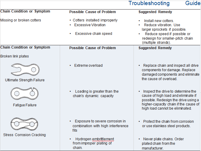
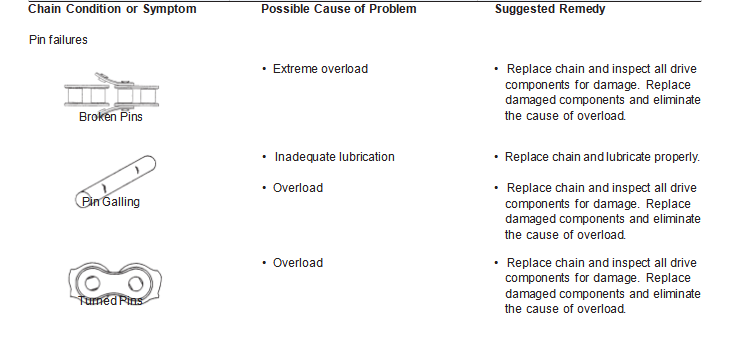
Troubleshooting Guide
Chain Condition or Symptom Rusted chain | Possible Cause of Problem • Exposed to moisture
• Water in lubricant
• Inadequate lubrication | Suggested Remedy • Replace chain with Nickel-Plated, Hydro-Service® , or Stainless Steel products. • Change lubricant. Protect lubrication system from water. Replace chain if necessary. • Provide or re-establish proper lubrication. |
Chain Condition or Symptom Excessive noise | Possible Cause of Problem • Obstruction • Loose casing or shaft mounts • Excessive chain slack • Excessive chain wear • Excessive sprocket wear • Sprocket misalignment
• Inadequate lubrication • Chain pitch is too large
• Too few sprocket teeth | Suggested Remedy • Inspect and remove obstruction. Replace chain if necessary. • Tighten fasteners. • Re-tension chain. • Replace chain. • Inspect chain for damage and replace sprockets. • Inspect chain and sprockets for damage and re-align sprockets and shafts. • Inspect chain. Clean and establish correct lubrication. • Redesign the drive using a smaller chain pitch (multiple strands), if possible. • Check to see if larger sprockets can be used. If not, redesign drive using a smaller chain pitch (multiple strands), if possible. |
Chain Condition or Symptom Wear on roller link plates and on one side of the sprocket tooth surface | Possible Cause of Problem • Sprocket misalignment | Suggested Remedy • Inspect chain and sprockets for damage and re-align sprockets and shafts. |
Chain Condition or Symptom Chain climbs the sprocket teeth |
Possible Cause of Problem • Excessive chain slack • Excessive chain wear • Excessive sprocket wear • Extreme overload | Suggested Remedy • Re-tension chain. • Replace chain. • Inspect chain for damage and replace sprockets. • Inspect the drive. Replace chain and eliminate the cause of overload. |
GIDI CHAIN LIMITED supply lots of roller chain, conveyor chain, Leaf Chain, welded chain, forged chain, Palm Oil Mill Chain, Hoisting Chain,Mine and Metallurgy Chain, etc. totaling over 3000 varieties. and 90% of chains are exported to worldwide, Which mainly export to Southeast Asia, European, North America, South America. Chains are welcomed by customers with the excellent quality. Our company owns more than 100 sets of advanced and professional manufacturing equipment, Perfect and rigorous QC system is implemented in every process from material purchasing to finished products packaging. Also, we have passed the ISO9001: 2015 Quality Management System Certification.
More Detail : www.gidi-chain.com
